


 |
|
The Design The construction of the John J. McCarthy Observatory (JJMO) was preceded by over two years of preparation and planning. Proposed as a public facility on town property, the Western Connecticut Chapter of the Society for Amateur Scientists (WCCSAS) solicited and received the unanimous endorsement of town officials, educators, as well as the general public. Privately financed, support came from community leaders, local businesses and private individuals in the form of monetary donations, goods and services. WCCSAS members visited other observatories, incorporating the best features and attributes into the JJMO design. The layout of the proposed facility evolved as multiple objectives and capabilities were reconciled with available resources. A scale model was constructed for visual presentation as well as for use in assessing the ergonomics of the design, identifying potential interferences, and evaluating public access and egress. Most challenging was the design objective to be fully compliant with ADA accessibility requirements, resulting in the incorporation of a wheelchair lift within the footprint of the dome. |
 |
|
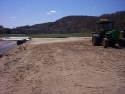
The Site Several locations were evaluated in and around the town of New Milford The site of the town's new high school (under construction at that time) was eventually selected as it provided good visibility, public access, security and also access to the high schools data and communication networks. The site was also found to have reasonably good "seeing" conditions despite its location on the Route 7 corridor in the Housatonic River valley. Groundbreaking took place on May 6, 2000. Two days later, the excavation for the telescope pier and building footings was completed and the forms assembled for the pour of the pier's base slab. |
 |
|
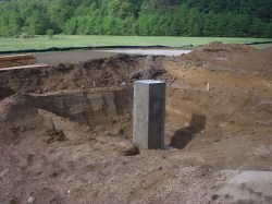
The Telescope Pier Weighing in at 20,000 pounds, the concrete pier is the most substantial component of the telescope mounting system and the most critical in providing a stable platform for the array of optical instruments and detectors. A number of pier designs and construction alternatives were evaluated. The elimination of any external sources of vibration was of primary concern with the proximity of the heavily traveled Route 7. The final design incorporated a three-tiered, geometric design. On May 9th, a two-foot thick rectangular base slab was poured at the bottom of the sandy excavation, approximately 10 feet below the final grade elevation. The following day, the forms for an 8-foot high rectangular column were erected on the base slab, bringing the pier up to grade level. A 42-inch high cylindrical column was added later, after the building foundation was poured, to extend the pier to the observing deck elevation. |
  |
|
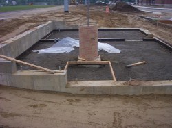
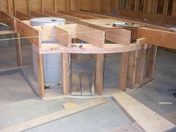
The Telescope Pier Parallel to the high school complex and adjacent Route 7, the long axis of the observatory building was aligned very nearly true north/south. Footings for the 34 by 22-foot building were poured on May 12th. An interior partition running east/west divided the structure into an observing and a control area. One-foot thick foundation stub walls were poured the following week. Two, three-inch and one, one-inch electrical/communication penetrations were installed on the west side of the north wall. The control room foundation was insulated and the cylindrical portion of the telescope pier poured on the 18th of May. The foundation was then backfilled with structural fill and the fill compacted. Grounding rods and wiring were installed along the perimeter and an interior power conduit/penetration installed between the two rooms. Temporary insulation was placed around the pier to isolate the pier structure from the floor (the insulation was later removed). A shallow pit was created south of the pier to accommodate the wheel chair lift. The floor was poured on the 25th of May. |
 |
|
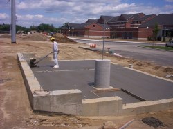
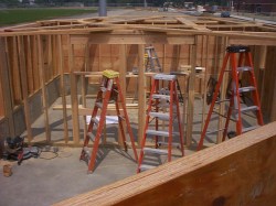
Above Grade Construction Framing of the building commenced on Memorial Day weekend with the raising of the west wall. An exterior doorway was framed to provide access to each room and a small window added on the east side of the control room wall. By the 31st, the framing for the exterior walls was complete along with the interior, dividing wall. The exterior of the building was covered with plywood sheathing. A vapor barrier would be added and the building finished with white masonry block. |
  |
|
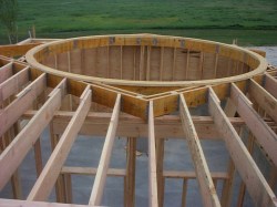
Dome Support (the Miskie) Ring The dome base ring was fabrication off site out of two layers of ľ inch plywood. To provide support for the ring and the steel observatory dome, Chief Designer Jeff Miskie designed a 14 sided, double walled, support ring fabricated out of 10 inch laminated veneer lumber (LVL) beams, set inside a LVL box structure supported by the three exterior walls of the observing room and the interior dividing wall. This highly unique design maximized the available floor area under the dome while providing a rigid support structure for the dome duration rotation. The acute angles for the individual segments required creative cutting techniques and almost all cuts were made with conventional tooling. However, segments with angles approaching 76° had to be taken to a local lumber mill for finishing. The LVL beams, support ring and base ring were assembled during the first week of June using simpson connectors. |
 |
|
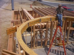
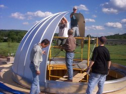
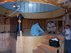
Ash Dome Rich Olson, President of the Ash Manufacturing Company, personally delivered the 16˝ -foot diameter, 1,625 pound dome on June 7th. The aluminized steel dome arrived as a stack of interlocking sphere segments, track and ring quadrants and in various containers and small packages. The circular wall plate, including the 28 ball-bearing rollers, was assembled and fastened to the dome base ring. The lower dome skirt assembly was fastened to the wall plate. The dome segments were then installed one at time, forming a rigid hemisphere as the edges interlocked. Twenty-eight bolts were used to fasten the structure to the LVL support ring. A shutter support ring was then installed to provide a guide track for the two piece shutter/windscreen assembly. A shutter motor was installed at the apex of the inside track and the azimuth motor placed along the southeast quadrant of the wall plate. Three days later the dome was unbolted and raised approximately 3 inches with hydraulic jacks to better accommodate the flashing for the roof. The surrounding roof was covered with an underlay, sealed and finished with a white stone. |
  |
|
Observing Deck An observing deck was constructed under the dome area of the observing room. The framing, comprised of an array of 2 x 10s, was covered with a 1˝-inch layer of screwed and glued plywood sheeting to form a rigid floor. The floor was eventually covered with a resilient, shock-absorbing tile. A circular stairwell was constructed under the edge of the dome to minimize its intrusion into the passageway between the two rooms as well as access to the wheelchair lift immediately south of the telescope pier. Railings were assembled out of laminated ash strips, fastened/clamped to the proper shape and hand finished. Heavy gage steel tubing was used for the balustrade. The stairwell was finished with birch plywood, as was the south wall of the observing room. Lexan was installed on the south railing to extend the wheel chair enclosure to deck level. A birch plywood facade was constructed to cover the LVL dome support ring and provide an aesthetic transition from the dome to the observing room ceiling. Red and white light cans were installed in the ceiling with additional lighting provided by wall fixtures and dome spot/work lights. On September 3rd, Tom Melsheimer, President of Merlin Controls, installed the dome automation system. The system, which interfaces with the telescope control software, is powered by a DC battery and is recharged by a solar panel affixed to the dome. |
 |
|
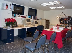
Control Room The control room is the environmentally controlled area of the observatory with heating and cooling provided by electric baseboard and a heat pump. Two observing windows were constructed in the south wall for viewing deck/telescope operations. The main power panel was installed on the west end of the north wall, immediately above the power/ communication penetrations. A full set of CAT5e and coax connection cables was installed throughout the observatory to allow for equipment connection with jacks convenient to every possible work location. Fiber optic and coaxial signal cables were run to the high school for remote video feeds, image downloads and digital remote control. High bandwidth fiber was installed for connecting to the Internet. Red, white and florescent lighting was installed in a suspended ceiling. Fixtures for a weather station and satellite dish were also provided for on the roof. The control room was furnished with several cabinets for the electronic components and interface panels, workstations with control, administration and graphics computers, video monitors, a technical library and a tool bench. |
 |
|
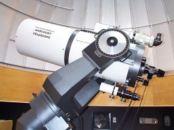
The Telescopes The observing room houses a computerized telescope mount system with three complementary telescopes and multiple video and still CCD imaging cameras for high-resolution astro-photography. The primary telescope is a 0.4-meter Schmidt-Cassegrain manufactured by the Mead Corporation. Mounted on top of the primary telescope is a 106mm refracting telescope made by Takahashi. Its superb coated optics compliment the capabilities of the primary telescope and is a superior instrument for lunar and planetary viewing. Mounted underneath the primary telescope is a specialized Helios I refracting telescope with integrated filters to allowed detailed observation of the Sun's surface. All three instruments are driven by the same computer controlled drive system and can be remotely driven as well. |
© - Copyright 2001 - Multimedia Productions Division, the Candlewood Group
All Rights Reserved